The old saying goes, “Make it as simple as possible – but no simpler.” I find that, especially where the project scope is unknown or undefined, keeping a simple design pattern is the difference between life and … unemployment.
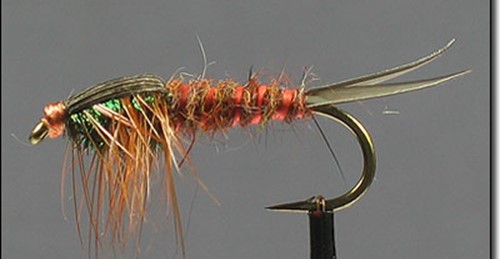
Take the fly fishing pattern below. You like?

Believe it or not, that’s not a real bug but a fishing fly – and I don’t want to think how long it took to tie this fly on to a hook. It’s meant to imitate this insect below.
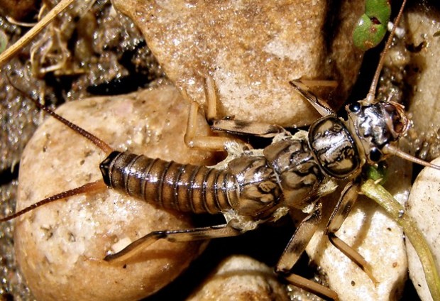
This bug may look a little like a cockroach to you, but to trout they’re like fat, juicy three inch long Twinkies. (Side note – if you haven’t experienced a stonefly hatch, you’re missing out in a buggy kind of way. These bugs grow for 2-3 years and then in late spring get a hankering for some college-style drugs and hot sex in the woods. En masse, by the thousands, they make their way from their cool river bottom home to the rivers edge, where a mass orgy ensues in the bushes. If you’re fortunate enough to be along the Deschutes River in central Oregon around that time – say April or May – they get everywhere – crawling around your clothing and hair, splatting noisily into the water, splashing noisily into the water and clumsily flying around like they’re drunk and/or stoned. After a long cold winter, this kind of feast is just what the doctor ordered – the trout hang out under trees, wait for the next clumsy splash to ring the dinner bell, and gorge. It may only last for a few days, a few weeks – but it’s by far
the best fishing of the year.)
So, let’s say you are standing on the banks of the Deschutes, 5-weight fly rod in hand, and you’ve got two flies in your hand – the awesome beautiful intricate fly above, and the ugly, homely, plain-looking lump of fur and feathers below. Which would be better to use – the fly above, or this fly?
Believe it or not, the more effective fly is the not the hyper-realistic IMITATIVE pattern at the top of the page – but the REPRESENTATIONAL pattern above. The fly above picks up light better, can be seen better in murky water – which is often the case in spring – and moves more realistically in the water. And best of all – if you lose the fly on a branch, you didn’t just waste two hours of your life!! So, you’d put fly A up on your mantelpiece as a work of art – but you’d actually hit the river with fly B.
In designing both UI’s and the data model to support them, I try to follow the same guidelines. I don’t want to get too emotionally attached to a particular model. If something is simple and needs refinements – or even a dramatic course adjustment – yes, I can refactor and adjust. But if it’s complex and multitiered, and a radical departure is called for – often, I have to start over. Big tears, remorse, heavy drinking ensue.
A Representational Manufacturing Process Model
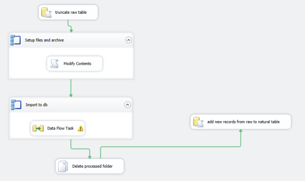
So, let me share a pattern used in a recent project. This isn’t a true pattern in the sense of Abstract-Factory-is-a-pattern or Async-And-Await, but illustrates the point of how to apply that Keep It Simple paradigm in a shopfloor model. The heart and soul of the project is kept in a Process/Step table (and a set of lookups):

Above, we have two key lookup tables – ProductType and Location. A ProductType
represents a product that we assemble – and a Location
is a specific area of the manufacturing floor. This is a standard many to many relationship built around the Process
key table – a product is assembled as part of a series of Processes in a series of Locations on the manufacturing floor. Each Process, in turn, can be broken down into a set of Steps. The StepType table is there primarily for the frontend – if the step needs to show a textbox, a checkbox, if validation needs to happen and on what range, etc. Naturally we could have broken this down into a more normalized store, particularly on the StepType table. But the table itself is not that large – and the cost in performance of splitting it out into separate tables wasn’t judged to be worth it. I’m happy with this – and if we have more requirements down the road that require a finer tuned approach, we can refactor as needed.
OK, so that represents a very rigid set of steps that a person on a floor will follow in assembling a part. But what happens when they want to introduce a change – even temporarily – to the way the part is assembled? For example, they may want to switch out a material, remove a step for a set of five consecutive serial numbers, or add a new step to double-check a fabric lining. These engineering tryouts could have a short shelf life – maybe just one assembled part as a trial – or they could become over time a permanent part of our process. We COULD have added these as new steps to our Steps table along with some new TryOut-specific attributes – but design-wise that seemed a little messy, since LTO’s don’t happen that often and there are so many attributes and special instructions that are LTO-specific – a lot of wasted space in our Steps table if we were to go down that route! So, I created a set of tables as below:

Look at this as a mirror reflection, somewhat distorted, of the Process-Step tables above. A TryOut
represents a batch of steps (TryOutStep) that a shopfloor tech will be following – either for a date range or, more commonly, for a series of new parts. There’s nothing here that’s dramatically new or different – it’s just a riff on the Process-Step table design, which itself is neither new or unique to our application. In our app, the TryOut will represent the parent information – the master portion – and the TryOutStep will be a list of detail records that a planner can modify on the fly. Because this is simple and generic, both the Step and the TryOutStep rows can be inserted at build-time as one lump of “I did this at this date for this part” kind of instructions.
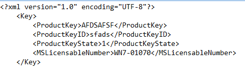
It’s here where we have to talk about Bill-Of-Materials patterns, another hoary and beaten-down pattern. See below. Some of this you will recognize from our old friend AdventureWorks – which in fact was some of our starting point:

This is very simple and doesn’t represent anything new that might shock a trout. A MaterialMaster
represents an individual part, a single screw, a film – anything that needs to be assembled as part of a hierarchy. What really matters is the BillOfMaterial
(BOM) table – which assembles these into a hierarchy using the ParentID field. We’ll get into the SerialNumbers and SNHistory table later – the important thing is, we have a list of parts as they’re assembled into a set of components, and from there into a finished good.
Thinking about Hierarchies
Here’s where the “…but no simpler” part of the “Keep it simple” saying comes in. We could have just thrown this together without any forethought – Cargo Cult
Programmer style. But we actually did think about this and our application before we started slamming out SQL. We checked the Microsoft SQL Server Bible 2008 by Paul Nielsen (a great resource, particularly the section on Traversing Hierarchies) and looked at some patterns:
-
Adjacency list
- This is the most popular and long-running pattern in the SQL community. Think Employee-to-Manager parent/child type relationships. This is otherwise known as the self-join pattern and it’s been around FOREVER, and remains the most popular solution.
- To get data out of this, think a subtree queries – but this breaks down past a certain number of levels – or use a recursive common table expression or a looping user-defined function (a recursive CTE is faster, the UDF solution offers more flexibility). You’d use a CTE solution when you need to look up and down the hierarchy in a very complex way.
- Pros – It’s very easy to manually decode and understand this pattern.
- Cons – It’s prone to data entry/cyclic errors, and not quite as performant as HierarchyID in retrieving subtrees. That being said, for our small list of parts, it returned results in milliseconds.
-
Materialized path
- Here instead of a Child/ParentID self-join pattern, you have a field called MaterializedPath (for example) with entries like “1,2,263”. See this article for more on the pattern.
- Returning a subtree is SUPER easy with this pattern, unlike the potentially-ugly adjacency list patterns – because all the information we need is in a single field, MatieralizedPath. A simple LIKE and a % wildcard in the WHERE clause gets this done.
- Pros – This would probably be your pattern of choice for multiple-level scenarios. It’s both durable and consistent – if you delete a record accidentally there’s no orphaned scenarios and the tree can be reconstructed easily. Paul Nielsen tends to favor this pattern, but it does take some learning to master.
- Cons – the key sizes can become quite complex, and simple operations like “get me the parent” become a little harder.
-
HierarchyID
- A new data type introduced in SQL 2008 specifically to solve these kinds of problems.
- Pros – It’s faster than adjacency list (but slower than Materialized Path).
- Cons – and these were significant for us – it embeds data within a binary data type so it’s more difficult to diagnose/navigate. Orphaned nodes happen, and are hard to reconstruct.
In summary – adjacency pairs are the most common, the easiest to understand. As Nielsen says, unless your requirement is very high performance, stick with this pattern. Materialized path is the choice where herarchies are core to the database and are used frequently in functions. HierarchyID to me is a loser, since the binary data type makes it difficult to debug/diagnose in the inevitable mixups (and its harder to track down and re-parent orphans). Kent Tegels did an excellent writeup on this using SQL Server 2008 with a pattern that used HierarchyID, but it wasn’t enough to swing the argument that way.
But the key thing is, we did have the argument and we did hash over the options. Once we did some research, the solution became clear – a simple Adjacency List was the way to go. For reporting, a simple Parts Explosion Report query did the trick. Again, we didn’t try anything radically complex, new or different – and I think if we would have, that would have been the first sign that we were on the right path. And by doing some research – and trying a pilot of Adjaceny List, Materialized Path and a HierarchyID set of queries – we knew the options, were comfortable with our solution and knew we weren’t missing out on something cooler/more performant.
Back To Our Model – Design Versus Real World
You would think at this point we’d be almost done. We’ve got the following entities –
- A product that needs to be assembled across a set of locations.
- A process that follows a set of steps before moving on to the next process.
- A set of steps (LTO’s) that can be followed on a temporary basis as an experiment.
- A list of parts that can be assembled as part of a component or finished good.
So far so good. But this represents what SHOULD be built – a model. It’s not reality, and doesn’t really show what’s built on the floor. For this, we need a Build History table.
This typically is bound up in the concept of a Work Order – like with the classic AdventureWorks model, where a bike is assembled from start to finish in an orderly series of steps from a single work order #. This assumes a very linear progression, all from a single order by a customer with a specific date. In real world manufacturing, this concept often doesn’t exist – and definitely didn’t with my project. Each component is assembled separately and placed in storage racks – its only in the final assembly stage that they’re linked together. So, while we definitely will include some form of an initiating action – a work order – in the future, our design initially really is based on just two tables – the SerialNumber and the BuildHistory table.
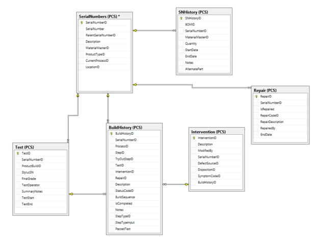
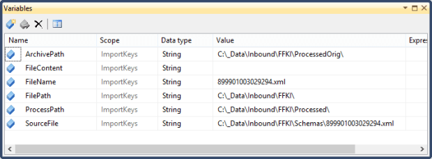
Above, SerialNumbers
is the key table. This contains an identifying serial number, which could represent any one of a set of components. But where the action really is at is the BuildHistory table. This starts out initially as a plain, bland copy of all the steps in our process model in the first section – linked with the StepID field. But there’s a set of attributes there that aren’t found in the Step table – things like StepTypeInput, PassedTest, IsCompleted, etc. This tells us what happened to the part as it hit this step of the process. Did it pass every test? Were there notes that the operator needs to jot down to help diagnose production issues? We chose to partition the SerialNumbers table into two pieces – the second (Test) shows test-specific attributes that only apply to final assemblies, including the final grade (A/B/F) and test start/end times. One SerialNumbers record (a part) can have one or more Interventions, where a defective part either has to be kicked onto a repair spur and either fixed and put back on the line or sent out for repairs. SNHistory tracks the record of our finished good as it is assembled into a chain of components and subassemblies.
I’m kind of going down an “ontogeny recapitulates phylogeny” rathole here. Let’s work backwards from the UI to explain this:
- So when an operator is ready to assemble a part, he clicks on a button to generate a serial number.
- A kickoff stored procedure generates a SN for that component and adds a single record to our SerialNumbers table, representing that part as built.
- It then pulls a set of steps from our process model (including any LTO’s) and fills the BuildHistory table with this sanitized, plain-vanilla list of steps the operator will be following.
- A barcode label for this part is printed and placed on the component.
- As the component travels along the assembly line, operators are scanning this label – and using the app form to enter in attributes to BuildHistory to show if the part passed its tests, what the environmental conditions were, and if it had to be kicked out for intervention/repair.
- All of this can be presented from a set of views and SSRS reports to show the lifecycle of a finished good and its individual components. Steps are modifiable, and so are processes. As each new product comes online, we add new processes and steps and BOM materials for that good – and keep it rolling.
Baking Cookies
In pitching this design to management, I used a cookies metaphor. When you go to make cookies, you pull out a recipe book, which has both a list of ingredients and a list of steps you need to follow. That’s great, but it may not represent what you actually do – you may be short of vanilla, or need to add an additional step to borrow some sugar from your neighbor. In our model, we have a list of steps (the Process/Step tables) to follow in our recipe, and a list of ingredients that we’ll use in an ideal situation (the BOM/Materials tables). But on any given day, when we pull out the recipe book, in the real world we’ll have the list of ingredients we ACTUALLY used (the SerialNumbers/SNHistory tables) and the list of steps we ACTUALLY followed in the heat of the moment (the BuildHistory table). Having a Step model to use as an ideal-world template, and a BuildHistory model to show it as-built, made the difference in creating a robust and performant application that was done in weeks, not months – and could survive numerous spec changes and new product rollouts.
Wrapping It Up
It’s kind of a mix of clunky and elegant still. But it’s survived a kind of Hunger Games-arena of instability and chaos for near on two months now with only minor tweaks. That’s because we started out simple. For example, the fact that the key BuildHistory table has a key/value pair design with the step description/input fields helped me initially when it came time to design and write the operations frontend. In my ASP.NET form listviews, I could read those bit properties – and show either a checkbox or a text entry field, and handle range validation appropriately for each step of the process.
I’m not as happy with the frontend, even though its mine, just because 1) it lacks a test project, which is massively irresponsible – and will cost us dearly in regression errors if not addressed in the near future, and 2) its using a SmartUI paradigm, WebForms, which offers quick turnaround but suffers in terms of UX, testability and clean design. We won the battle in rolling something out the door soon – it took about six weeks from design to ‘completion’ – but may lose the war if we can’t buy out a few weeks to rethink the frontend. Down the road I’m actively looking at Single Page Application UI or something using a MVC/MVVM pattern. Since the backend is solid, I’m not that worried – we’ll come up with something clean and nifty soon enough.
The best fishing flies aren’t imitative, but are representational. If the fly could be one of any number of insects, you’ll have more success on the water versus targeting one hyper-specialized approach. And I feel the same thing applies to software – you’ll have more success and waste less time by (at least initially) following a generic, nonspecific approach in your design.